Jump to content
Do Not Sell My Personal Information

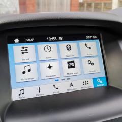
How To: Focus MK3 SYNC 3 upgrade for Bluetooth Voice Control (BVC) cars from 2011, 2012 and 2013


JPW
 Share

Recommended Posts

😎 Focus MK3 bluetooth Voice Control (BVC) non-SYNC to SYNC 3 😎

Guide last updated on 6th March 2021

Let's get the boring stuff out of the way... Please be aware this how to is provided as advice and guidance only. Should you wish to proceed you do so at your own risk and I am not to be held responsible for any issues that arise. As this requires changes to the factory wiring of your car it should only be carried out if you are confident in doing so. That said, if you face any issues or have any questions I will do my best to assist, as I'm sure other members will.

I would like to say thanks to everyone who has posted similar guides regarding upgrading SYNC 1 to SYNC 2/3 as this allowed me to understand the basic requirements and get to a point where I could move forward. In particular @Luke_Anderson, @Phil21185 and @JW1982.

Please make sure you read the whole post before commencing so you fully understand what you need to do.

Introduction

All 2011, most 2012 and some 2013 Focus MK3 cars in the UK (and possibly EU) were built without the SYNC 1 audio system. Instead, they have a BVC (bluetooth and Voice Control) system that looks similar but has different components and wiring harnesses.

My car is a UK, 2012 Focus MK3 Titanium with Sony radio, factory navigation, dab and reverse camera. You don't need to have the same spec car to proceed, but you must at least have the factory fitted BVC system (not SYNC).

You an easily determine whether your car has BVC or SYNC 1 by the steering wheel controls. BVC has a separate stalk for the volume and audio controls, whereas SYNC1 uses the right hand d-pad on the wheel itself (with the voice control button):

image.thumb.png.dd2708a0ee137f281fe3ab547d50ffa6.png

Now you've determined your car is equipped with BVC and you want to upgrade to SYNC 3, continue below! If you have SYNC 1 rather than BVC, go here.

Other Ford models of a similar year, CMAX, Kuga etc can also be upgraded from to SYNC 3, but the parts list is slightly different. Ask here for more details!

Parts required

The SYNC 3 system is made up of a number of different but linked parts. You will need to purchase all of these in order to have a working system. I have included the part numbers I used, but there are a number of variances from different vehicles. You can purchase the touch screen, APIM, ACM, USB Hub and Bezel from any 2016 - 2018 (not 2019+) Ford SYNC 3 equipped vehicle. Only the bracket and front fascia is specific to the Focus MK3 and is different than CMAX, Kuga etc. There are also some tools/bits required.

8" Touch Screen: GM5T-18B955-SB This is the main touch screen required for SYNC 3.

 TouchScreen.jpg.c457e380238690e06859b8ba46ffc913.jpg


APIM: JM5T-14G370-GNC The APIM is attached to the back of the touch screen and is the brains of SYNC 3. Has navigation support.

APIM.jpg.97f2254a551fa9aeee4d0209178d5d1a.jpg

 
ACM (Radio): F1BT-18C815-LP This handles the CD, DAB and FM input, as well as the output to your Speakers.

 ACM.jpg.5773413a3db7efc861e30d05f75cccc0.jpg


USB Hub: Finis 2026703 Required for USB connectivity including Android Auto / Apple Carplay.

usb_hub.jpg.46b805e197e55b8b947d7040f06a4efd.jpg
 
USB Bezel: Finis 5326708 This is a trim piece in which the new USB hub fits in to. Replaces existing USB/line-in inside centre armrest.

Bezel.jpg.302ef451dfb6c92992451f97d298cb85.jpg

Front Fascia: F1ET-18K811-HC This is the front fascia with the radio control buttons and hazard switch.

Fascia.jpg.f30f0de6a80f400722131edfbd1e928d.jpg


Bracket: Finis 1895997 Required in order to seat the new 8 touchscreen and radio in the existing opening.

Bracket.jpg.41c5ef4d34fb7de3692d438e5e97b05b.jpg


Bottom trim piece: FIEB-A046B74-ACW This is a small cover for the bottom of the front fascia panel.

Trim.jpg.2a8d384033790a3802e15fc5c1a2c522.jpg


2.5m/3m Mini USB to Mini USB Cable: eBay or wherever Required for connectivity between the media hub and the APIM.

USB_cable.jpg.09fa45c9fea8b5ed31b7f0062cddd051.jpg
GPS Antenna (Fakra connector): amazon (click here) GPS for the sat nav function of APIM.

GPS.jpg.0b41812dc01d6870c1f35f031a86b9cb.jpg 


SYNC Harness: InCarTech(click here) Required to make the new SYNC APIM connector.

54pincable.thumb.jpg.0233a455f4084f97ac207485a1c22cc9.jpg


Fakra to RCA converter: Amazon (click here) (if you have a reverse camera).

RCA.jpg.1f5a4c3f175a63ad6bd01e109ba96ba8.jpg


ELM327 ODB2 Diagnostic Connector: amazon (click here) Required to update your car settings after installation.

ELM327.jpg.ed1c9b69043a128ab094e73b54623d5d.jpg
 

Female to female jumper wires: amazon (click here) Required to make some connectors for the ACM accessory pins.

jumper.jpg.562783678b2eba5d56d20eea52126490.jpg

4mm Insulated crimp connectors: Screwfix (click here) Required for joining / splicing the wires together.

crimp.jpg.f0c74731044a6a4f49d6bb8b25fd5f54.jpg


Crimp Tool: Screwfix (click here) Required for crimp connectors above.

crimptool.jpg.955e2aa3fb62911090cd90e75ba51964.jpg


Step 1 - Remove the existing system

Here is the factory fitted system before I began:

IMG_20191127_100238.thumb.jpg.644a34166678de3b6d868516d74ee529.jpg    IMG_20191127_100200.thumb.jpg.b1e27b53e0cb2075e4d97a2580792039.jpg

IMG_20191127_100212_1.thumb.jpg.4c1ad71b5c941fd2b559da77b8630365.jpg

Lets start by removing the existing components. This is the screen, ACM and bluetooth module:

Start by removing the small plastic grill underneath the existing front fascia (its just above the heater controls). This reveals two screws which you need to remove. All screws are torx fittings.

The front fascia can now be removed. If you have a SD card (for maps) plugged in above on your existing screen, remove first. Gently pull the front fascia away from the dash at the bottom where you removed the screws. It will come away fairly easy and then just ease it out at the top/sides. Note: There is a wire connected to the rear of the front fascia, take a look behind it (might be a squeeze) and unclip it before removing the fascia completely. You are left with this:

IMG_20191127_100328.thumb.jpg.8507e7c03e2e50eed6d63f635428ac73.jpg

Next, lets remove the ACM (radio). Remove the two screws to the bottom left/right of the screen and pull the silver radio out. On the rear, there is either one or two (depending on year) large connectors and one or two (white/black) antenna connectors. Unclip these. These connections are known as Fakra and to release them you have to press down hard on the little plastic tab on the connector itself, whilst pulling away from the ACM. With everything removed you can now remove the ACM:

IMG_20191127_100502.thumb.jpg.985aa36ad9809f31ffb04f9f4d74b504.jpg

Next, remove the screen. There are four screws that hold the screen in it's bracket so go ahead and remove these. Gently pull the screen forward and on the rear you'll see some connections:

IMG_20191119_173805.thumb.jpg.73d4a2a3493671295eb1ee3ea4caf751.jpg

The blue connector is for the GPS (if you have sat nav). The black cable is the FM/DAB antenna and the pink cable is a loop down to the ACM which is no longer used and can be taped up. The beige/green connector is the reverse camera (if you have it). There is also a black 12-pin (FCDIM) connector which can be removed by releasing the little clip and pulling out. The area should now be clear:

IMG_20191127_101048.thumb.jpg.52c8cf195366210e42b24039d0a2c64f.jpg

Next, remove the heater control panel. There are two screws visible, and one that is hidden behind the trim just above the gear surround. You need to remove the gear surround trim. Gently prise it up with your finger nails or a plastic tool to avoid scratches. Be careful, the clips are fragile.

This reveals a small hex nut (bottom right of picture) you need to remove. Go ahead and do so:

IMG_20191127_103223.thumb.jpg.4ec2c581a6308735ed5eb2ccc3218f9f.jpg

Next, you can remove the plastic trim to the right of the gear surround to reveal the third screw you need to remove:

IMG_20191127_103954.thumb.jpg.9d6b548adbe2d9c5780cc9263b3734b4.jpg

You can now pull the heater controls forward a little. On the rear there are four connectors that need removing. Unclip and remove.

Next, you need to remove the bluetooth module. Remove the single screw in the centre of the module, which looks like this:

IMG_20191203_124300.thumb.jpg.bee0cb1ebdc52bd883c4357e8f8b62ca.jpg

Remove the large connector and the USB connector from the bluetooth module. With both these unplugged you can now fully remove the bluetooth module.

That's everything removed! Grab a cuppa and a snack as it will take a while for the next part.


Step 2 - Modify existing wiring (point of no return!)

You now need to modify the existing wiring. The first task is to reroute the 54-pin connector (which was removed from the bluetooth module) up to where the old ACM (radio) used to be. There are some cable ties on the harness so you might need to use some long nose pliers to twist these off. There is enough length to do this comfortably.

Now, let's start with the remap of the wiring. I have created a handy table of everything you need to connect. See below:

https://docs.google.com/spreadsheets/d/1pmq3cnwcSwA-rguIIyzGJgG8M4r2XQRxMKk1P7c4RPc/edit?usp=sharing

To help, this photo identifies all the cables:

layout.thumb.jpg.987dda51555c2f192c38e19882d0758a.jpg

You can do some of this in your house before heading to the car!

Let's begin with the 54-pin APIM harness you purchased and cut all the wires as per the red dotted line:
 

SyncHarness2.jpg.2f1b3f702be94372b3c861f86a7957a3.jpg


Next, remove the black cloth tape wrapped around this connector and label all the wires you need to use. Not all 54 wires are used (see APIM wiring table above). You can see which is pin 1 to 54 in the following image:

APIM54.thumb.jpg.6aae43c1aaa3d6b45d6f48a26bf2b8d8.jpg


I labelled each wire which allowed me to map what goes to where.  It would have been difficult without doing this!

Labels.thumb.jpg.40301072916dcc4a90da1c864a2530e0.jpg

For reach required pin as per the APIM table above, cut back about 10 mm of wire and insert in to the red crimp connector. Using the crimp tool (4 mm setting) crimp down to get a tight grip on the bare wire:

example_crimp.thumb.jpg.9171f8828c9ae67f4bad53e4d4cff440.jpg

Next, inside the car, you need to join each wire with the wire that exists inside the existing wiring harnesses of the car. Remove the outer black cap around the original 54-pin connector you removed from the bluetooth module and you'll get access to the wires:

btvm.thumb.jpg.19b49f1f1083296e3edbe383bdd4b573.jpg

Cut the wires close to the blue connector, one at a time, strip 10 mm and join it with the corresponding crimp connector you prepared on the Amazon 54-pin APIM connector. E.g. Pin 18 on the above connector should be joined with pin 1 on the APIM connector.

Next, you need to cut the wires off the end of the old connector that went in to the back of the FCDIM (screen). Label them before cutting again so you know which is which.

Again, one at a time, strip 10 mm and join it with the corresponding crimp connectors you prepared on the Amazon 54-pin APIM connector. Note that wires 4 and 5 from the old FCDIM do not go in to the APIM connector, these are used for the the Front Fascia connector. For now, crimp a new crimp connector on these two wires so they are ready to join later.

Next, you need to modify the existing Front fascia connector. This is the 8-pin connector that plugs in to the front fascia with the radio controls and hazard switch etc. Remove the red protective cap from the end of the harness:

FCDIMPinout.thumb.jpg.ac45ec232ab95920614a2812d0dc473b.jpg

Strip back the grey cloth tape by around 10 cm on the wiring harness so you can get access to the wires. You need to cut and strip the wire that currently goes in to pin 7 and join the wire coming out of the FCDIM connector pin 4 that you prepared in the last step.

You then need to cut the wire in pin 2 and pop the remaining wire and pin out of the connector itself. From the front of the connector you'll see the silver pin. Insert a small flat screwdriver or paperclip and lift he pin up and pull it out the front. You need to re-insert this in to the empty pin 4 on the connector. Once done, strip the wire you just pushed in to pin 4 and join with pin 5 from the old FCDIM you prepared in the last step.

Side note...

You will see that on the new front fascia you'll no longer have an unlock/lock button like the original faceplate. This is because the facelift MK3 models have the lock/unlock button incorporated in the drivers door card so it was never present on the new front fascia.

So, to get a working lock/unlock button back, you can purchase a simple momentary button with a built-in LED such as this from Amazon.

I mounted it just under the gear stick so the driver or the passenger can easily operate it:

image.thumb.png.0dcf6a5af03d7a6573a4e67d07379082.png

image.thumb.png.e57e5b2c1261443076125885bddc3606.png

You need to wire the momentary button as follows:

  • 12V join this to the wire that used to go in to pin 2 of your FCIM connector (white/yellow)
  • 0V join this to any ground wire
  • C join this to the 0V (ground) above
  • NC join this to the wire that used to go in to pin 6 of your FCIM connector (brown)
  • NO not used

The LED brightness changes when locked, and dims when unlocked so you can tell the current lock state.


Now, we need to tap in to the OBD2 port for the MS-CAN and HS-CAN wires. The OBD2 port is behind the little pull down storage compartment near the drivers knee (nearest the door) Youtube video - click here. You'll need to carefully strip back some of the copper wire on pins 3, 11, 6 and 14 and run four lengths of new wire from behind the dash where the other wires are. Join these to the stripped copper as per the MS-CAN and HS-CAN on the wiring table. Do not cut any wires going in to the OBD2 port as you still need this to function as normal.

Next, let's get the new USB Hub installed. In the centre armrest, we need to remove the existing USB and Line-In hub. Using a small flat screwdriver or plastic pry tool lever under the panel and it will lift up. The cables are tight, so you'll need to twist it around a little so you can get your fingers in to unclip the existing two connectors I found the USB port to be a real pain to unclip, so ended up snipping it. We cannot re-use these connectors therefore it doesn't matter if you damage them when trying to remove:

OldUSBHub.thumb.jpg.fe43c80cb49b03e26c25232abffd50fe.jpg

With the old USB hub removed we now need to run the wires that supply the new hub. Using 2 new wires, run these all the way from where the USB hub will go back to behind the dash where the other wires are. At the same time run the mini USB cable to the same points. I was able to run these cables along the underside edge of the centre console where the gear stick and armrest is. I didn't need to remove any of it. The tricky part was feeding the cable up to the hole where the new USB hub will go.

Take two of your female jumper wires and cut one end off. Strip back 10 mm and join it with the end of the new wire you ran to the new hub. Same for the second wire. This will leave you with two wires that look like this:

usbjumperwire.jpg.94994971b123421960ef1bfa3e92f6ce.jpg

Push one wire to pin 1 of the USB hub, and the other to pin 4 of the USB hub. I used some duct / gaffer tape to make sure these don't move once pushed in.

USBHubPinout.thumb.jpg.9ee706631ac4a0eb3dae9d693f7cdee2.jpg


At the other end, crimp the wire from USB hub pin 1 to the APIM connector pin 8, and USB hub pin 4 to the APIM connector pin 38.

Connect one end of the mini USB cable to the black USB socket on the hub, and leave the other end in the dash for later.

Once the wires are in place, install the USB bezel in to the hole, and then secure the new USB hub in to the bezel:

IMG_20191205_222607.thumb.jpg.4a08db4530433f8f99197da5bd0dde0c.jpg

If you're still with me, well done. You're nearly done with the wiring!

Finally, take six female jumper wires, cut the ends off, strip and join these to the six remaining wires in the 54-pin APIM connector. As per the mapping table above these should be 3, 4, 23, 24, 25 and 26.

All the wiring mods are complete and we're ready to plug everything in! It surely must be time for another brew...

If you purchased the Screen / APIM / ACM / Bracket separately now is the time to connect these together so they ready to slot in to the dash:

APIMBack.thumb.jpg.ed3643c77c14eef97220a9942dc3a0da.jpg

Sitting in the passenger seat, slide the unit in to the dash side on, so you can see the back of it from your seat. Plug the blue GPS antenna in to the top left of the APIM. Plug the USB cable in to the black USB socket. Plug the 54-pin APIM connector in to the large black socket. 

On the ACM, plug in the black fakra connector (from the old FCDIM) and the white fakra connector. Connect the large black ACM connector. Finally, you should have six wires loose from the 54-pin APIM connector, all with female jumper ends on. Connect these to pins 12, 13, 21, 25 and 26 as per the mapping table. Use some more duct / gaffer tape to secure them in. (Yes, I'm aware its probably better to make a proper connector with these in, but I ran out of time. Do so if you wish):

ACMWires.thumb.jpg.c63264045fcd9fcc37181806d4bf27fc.jpg

Carefully turn the unit so the screen is facing you and slide it in to the dash. There are some plastic guides/tabs where it slots in so be sure its in these. When doing so make sure the 8-pin Front Fascia connector doesn't get lost behind he unit as you need to connect that when you re-place this fascia:

IMG_20191207_140048.thumb.jpg.f022c4386ed88b48ac0ebcdeb4cdfe4b.jpg

The big moment...

Heighten your senses and turn on your ignition. The unit should now turn on and boot up. Look and smell for anything untoward. Provided the wiring mapping tables have been followed and the crimp connectors done properly you shouldn't have any issues.

Don't worry about any errors/pop-ups/warnings at this stage as this is to be expected. Using the touchscreen, choose Audio and Sources, and tune to a station. Check you have sound etc.

Updating the settings

We now need to 'program' the car in order for it to work correctly, as it still thinks you have the old bluetooth module and small screen installed. You'll need a laptop on Windows. In order to update the car settings we need to find a suitable 'donor' car. This means take a look on Autotrader or some other used car site and look for a Focus MK3 (2016-2018 year) with a similar same spec as your own car (like stop/start. manual transmission etc). Make a note of the registration/licence plate number and head over to the Ford Etis website at http://www.etis.ford.com/vehicleRegSelector.do

Enter the registration number and click submit. On the right hand side, it will now show you the long VIN number (usually starts with WF). Make a note of this.

Next, head over to the Motorcraft AS-Built website at https://www.motorcraftservice.com/AsBuilt. Enter the VIN and click Submit. It may take a few minutes to load so be patient. It will come back with a page with a blue Download File icon. Click this and save to your laptop.

We are now ready to plug the laptop in to the car and upload the new settings. Download and install/unzip the following applications:

Turn the ignition on (accessory mode) but not the engine. Connect the ELM37 cable to the Focus Diagnostic port, making sure the switch on the ELM327 device is set to the HS-CAN (High) option This is located behind a small door on the drivers side dash, under the steering wheel. Youtube video - click here.

Plug the USB in to your laptop and it should self-install the driver. Open up FORScan and click the Connect icon. At this point it should say Connected to car, and load some information in. It will ask you to save a profile, so give it any name you like.

On the left hand side, click the Computer chip icon. Click the option called APIM (AS-Built format) and then click the Run service Procedure icon at the bottom. Accept the warnings and proceed.

Next, before you do anything further, click the Save all button to save a copy of your existing APIM config. Save this to your laptop named "Backup - original" or similar.

Next, click the Load file button and select the *.ab file you downloaded from the Motorcraft website above. Click Write All and your SYNC 3 unit will automatically reboot.

You will note that the instrument cluster changes colour to a darker blue gradient. This is normal and expected and is just part of the settings change. This is how it looks on newer Focus MK3's. The functionality remains unchanged. Also note, the right-side steering wheel directional buttons are no longer functional as these are now moved to the left-side directional buttons (the ones that used to control your old radio). Again, this is how it works in the newer Focus cars.

Close FORScan and open the FoCCCus application. Click connect and load the Central config tab. Click Read from BCM. Do not panic when your instrument cluster makes some warning tones and alerts - this is normal. Yes, it appears odd, but it is normal procedure when programming. As above, before you change anything, create a backup file of your Central config first.

In the Central Configuration you should now see a load of options, filled in with your car's current configuration. Change ONLY the existing settings:

  • 123 – Audio Aux Input = 01 (without)
  • 125 – DAB Radio System = 01 (without)
  • 154 – Module USB = 01 (without)
  • 157 – Bluetooth Handsfree = 01 (without)
  • 172 – Front Display = 09 (DM8 with nav)
  • 214 – ICP = 09

Click Write to BCM, wait for it to complete, then Write to IPC.

At this point the programming is done. You can remove the ELM327 cable. Check everything is working including Volume Control on your steering wheel etc. Check you can make/receive calls through the SYNC 3 unit, load the navigation app, pair your phone etc.

All that remains is to get your front fascia fitted back in to make it all look brilliant. One snag, the fascia needs a little trimming in order to fit nicely. If you try and fit it, you'll see at the bottom what is stopping it from going in flush. I have posted an image below (credit to @Phil21185). I just used a junior hacksaw but you could use a dremel/multi-tool etc.

FasciaCut.thumb.jpg.7a26f6f5fa248be183897bdce0f2a8a5.jpg


FasciaCut2.thumb.jpg.7aaf3365c3d4b85d69df6aa3645016cb.jpg

With the panel trimmed you should now be able to fit the fascia back in place. Remember to re-connect the 8 pin connector to the back of this else your buttons / hazard switch won't work. Finally, push the bottom trim piece up and in to the gap above the heater control to tidy everything up.

The Results

IMG_20191207_135838.thumb.jpg.c731a2c1b50aac5614de99d619ea50b5.jpg

IMG_20191207_135817.thumb.jpg.e99f6e1431f07b8267885279498b7523.jpg

IMG_20191207_135907.thumb.jpg.213ed043d19f6b8f174ac4d4a2e7163b.jpg

Night.thumb.jpg.3d6500e6ea505108ba34219e036c46ae.jpg

Wow, that was a super long post. I know it may look daunting, but it's not difficult at all and is very much worth the effort. It looks like a lot more work than it is just because I wanted to go in to every detail to make it easy for you. I have double checked the instructions and apologise if I have missed anything!

Good luck!


  • Like 3
  • Thanks 2
Link to comment
Share on other sites


Hats off to you my friend, that is a fantastic guide! 

Link to comment
Share on other sites

1 hour ago, Luke_Anderson said:

Hats off to you my friend, that is a fantastic guide! 

Thanks Luke. Your guide inspired me to see if it can be done.

I must admit it took around 6 days to write up the guide, an hour per day when I got chance!

Did you end up on SYNC 3 in the end or stick with 2? Have you been able to update he software and maps?

Cheers

  • Thanks 1
Link to comment
Share on other sites


I went to sync 3 about a week after sync 2, maps and software updates are easy enough to do manually 👍🏻👍🏻

Link to comment
Share on other sites

9 minutes ago, Luke_Anderson said:

I went to sync 3 about a week after sync 2, maps and software updates are easy enough to do manually 👍🏻👍🏻

Did you use the same VIN you used for the As-Built data (from a donor / car you found online with same spec?)

Once you do the SYNC 3 update, you have to upload the file that is saved on the USB to the Ford site, but modify it with the donor VIN also? It should then offer you the maps?

Thanks

James

Link to comment
Share on other sites

Tried that one but the maps download for F8 gives a 404...


Link to comment
Share on other sites

What a brilliant guide, fair play James!

Do you (or any of the other clever people on here) know if it is possible to do anything with a Mk3 with no BT/VC and no Sync? I have so many regrets about buying a second hand basic b*tch model two years ago - it was a very rushed purchase. 

I literally had to add alloys because it came with steel wheels. I also added cruise control at the start of this year using a guide from this website. Parking sensors, rear camera and bluetooth would be the dream but having the basic model seems to hinder a lot of that!

Kevin

Link to comment
Share on other sites

Hi Kevin

Can you post a pic of your current dashboard so we can see the screen/front panel etc?

If its a 2014 I'm sure it must be SYNC 1. I wasn't aware any trim came without SYNC after 2013...

If you PM me your reg I can check the Ford system to get an answer.

James

  • Thanks 1
Link to comment
Share on other sites

Hi James,

I've got a "sound" button where a "phone" button would normally be if the car had bluetooth. Hopefully the pictures came out clear in the dark. 


I'll PM you my reg details now, thanks a mill. 


Kevin

Screenshot_20191213-213855.jpg

Screenshot_20191213-213959.jpg

Link to comment
Share on other sites

Hi Kevin

So, having checked your reg number, it does appear this is a basic model that doesn't have bluetooth or Sync. Few and far between! Would be interesting to know if the wiring is there as if so, we could still get something working...

Link to comment
Share on other sites


Being rare makes it more valuable right? Haha 

I'll get the dash off at some stage over Christmas and see what wires are there. Wouldn't be surprised if there was a hamster running the thing. 

Jokes aside, I still love the car. Had it remapped so she's fairly nippy and I like how easy (with this website, I'd be lost on my own) it is to add things to it! I was chuffed to bits when the cruise control I added worked. 

Link to comment
Share on other sites

Yeah, well done on the cruise control. Practically anything can be retrofitted in these cars as they are modular. You just need the parts, wiring (if not present) and reprogram it via the OBD2 interface.

Link to comment
Share on other sites

I've now got the software and maps updated so all working and current!

Link to comment
Share on other sites

Hi. I am wanting to do the upgrade from non sync to sync 3 I’ve managed to source all the parts needed except for the mini usb to mini usb cable, any advice would be great 

Link to comment
Share on other sites

18 minutes ago, Ben2499 said:

Hi. I am wanting to do the upgrade from non sync to sync 3 I’ve managed to source all the parts needed except for the mini usb to mini usb cable, any advice would be great 

Hi Ben

I had the same problem and ended up ordering overseas but It would be easier to just get a male to male USB A to A cable, then a female USB A to male Mini USB for each end.

1 x https://www.amazon.co.uk/Rankie-Type-Male-Data-Cable-Black/dp/B01KXAYL74

2 x https://www.amazon.co.uk/Hama-39626-Adaptor-Cable-Female/dp/B004L2KSA0

Good luck!

Link to comment
Share on other sites

Thank you, is it worth the time, hassle and money. The only reason I want to do it is so I don’t have to use my external sat nav. As well as it looks so much smarter 

Link to comment
Share on other sites

Massively worth it. It doesn't take as long as it might look in the guide. Remember, I had to spend days figuring out all the wiring and how it can all be fitted.

Having known what I now know as per the how to, I reckon you could easily get it all done in a working day.

You don't have to bother with the usb media hub if you don't need usb input too.

Link to comment
Share on other sites

Hi james, I am wondering if you can help with my current stereo it don’t have gps antenna, where as with the equipment I’ve sourced for the sync 3 concersion it has the antenna, where do I place the antenna. 
 

the only worry I have with this all is the wiring and re-wiring. Luckily I am I suing prime audio based in Yorkshire to fit/ program sync 3 along with after market reverse camera. 
 

kind regards 

Ben

Link to comment
Share on other sites

Hi @Ben2499

You can place it anywhere really, most people place it above the new SYNC 3 unit on the plastic at inside back of the dash.

Is it just a small square antenna with a blue camera plug on it?

James

Link to comment
Share on other sites

Yes it is I believe, I followed your link to the one on amazon
 

with regards to the additional wiring that you used the old Ethernet cable what type of cable/wire would you recommend if I was to buy the additional wiring.  

Link to comment
Share on other sites

Latest Deals

Ford UK Shop for genuine Ford parts & accessories

Disclaimer: As the club is an eBay Partner, The club may be compensated if you make a purchase via the club

Join the conversation

You can post now and register later. If you have an account, sign in now to post with your account.

Guest
Reply to this topic...

×   Pasted as rich text.   Paste as plain text instead

  Only 75 emoji are allowed.

×   Your link has been automatically embedded.   Display as a link instead

×   Your previous content has been restored.   Clear editor

×   You cannot paste images directly. Upload or insert images from URL.

 Share


×
×
  • Create New...

Forums


News


Membership