JPW Posted January 9, 2020 Author Share Posted January 9, 2020 Yeah, sorry, I am getting a momentary switch not latching. A 12mm one turned up today but it's much smaller than I imagine, like too small to press with a finger without using a your finger nail. Need at least 19mm but probably bigger to be a comfortable press. 1 Quote Link to comment Share on other sites More sharing options...
Tommo17 Posted January 10, 2020 Share Posted January 10, 2020 On 1/5/2020 at 8:42 PM, Nathan Buffery said: To be honest I'm surprised there isn't a inline connection, but I can't see one on the diagram. If your lucky the wires will pass around behind your glove box. I wonder if @Tommo17 might have a better idea as i think he said he has a spare wiring harness. I’ve still got the spare floor harness. Will be going to the skip soon. Quote Link to comment Share on other sites More sharing options...
JPW Posted January 10, 2020 Author Share Posted January 10, 2020 So, I've purchased this 12v momentary switch: https://www.amazon.co.uk/gp/product/B07GLPBPPZ/ref=ppx_yo_dt_b_asin_title_o00_s00?ie=UTF8&psc=1 and plan to mount it in the car someplace. I have 3 wires from the car - Central locking LED status indicator (originally from FCIM 2) Door lock/unlock signal (originally from FCIM 6) Ground (spliced from from FCIM 5) What I want is to wire the door lock/unlock signal to the button press and the central locking LED status indicator wire to the LED light on the switch so that it's only on when the car is locked. On the old radio fascia, I presume it just sends power down the central locking LED status indicator when the car is locked... I also have a ground wire. Can anyone confirm the pin out? Quote Link to comment Share on other sites More sharing options...
Nathan Buffery Posted January 10, 2020 Share Posted January 10, 2020 Yep. You want to connect the ground wire to common and also led neutral. Door lock signal to "NO" and the central locking LED to the LED live. The signal works by making contact with the ground. Quote Link to comment Share on other sites More sharing options...
JPW Posted January 10, 2020 Author Share Posted January 10, 2020 Is common definitely to ground and not live? Is this so no 12v signal is pushed down the wire when you press the button? Quote Link to comment Share on other sites More sharing options...
Nathan Buffery Posted January 10, 2020 Share Posted January 10, 2020 Yeah I'm pretty sure the switch works by the switch wire picking up the ground. This is the case with the HRS, the stop start and parking switches. It probably saves running a live out to each switch, as the ground is mostly there already for the illumination. Quote Link to comment Share on other sites More sharing options...
JPW Posted January 11, 2020 Author Share Posted January 11, 2020 Fitted and working 🙂 There is a very faint led coming through to the button when the doors are unlocked, and then it fully illuminates when doors are locked. Pushing the button toggles correctly. Slightly concerned that this very faint LED light stays on when car is locked externally and you walk away. Checked 10 mins later and still on. Hoping it won't drain the battery. Strange that any signal is getting through when the car is totally off and youve locked up. Thoughts? I can't remember whether the original radio fascia LED lock button stayed lit after locking the car with the key... James Quote Link to comment Share on other sites More sharing options...
Nathan Buffery Posted January 11, 2020 Share Posted January 11, 2020 48 minutes ago, JPW said: Slightly concerned that this very faint LED light stays on when car is locked externally and you walk away. Checked 10 mins later and still on. Hoping it won't drain the battery. Strange that any signal is getting through when the car is totally off and youve locked up. Thoughts? Very strange. Are there any fault codes? I think some of the switches I looked at had an option of half led when off and full when on, but as you say, there should be no voltage getting to it when the car is locked. Quote Link to comment Share on other sites More sharing options...
JPW Posted January 11, 2020 Author Share Posted January 11, 2020 Looks like it does similar to the 12v socket. Stays on a short while before properly going off. Went out another few minutes after and it was properly off. Couldit be to do with the fact I spliced the ground front the front 12v socket (as I mounted it close by)? Would have thought ground is ground... The positive supply comes from the BCM through for the LED lock status... Quote Link to comment Share on other sites More sharing options...
Nathan Buffery Posted January 11, 2020 Share Posted January 11, 2020 So does it properly go off now? Not sure if you need to use the ground from the switch, I'm unsure if this is monitored for faults. I have had led faults before so it's possible. Quote Link to comment Share on other sites More sharing options...
JPW Posted January 11, 2020 Author Share Posted January 11, 2020 Yeah, it does go off after about 15 mins... 1 Quote Link to comment Share on other sites More sharing options...
Monks600 Posted January 11, 2020 Share Posted January 11, 2020 Yeah, it does go off after about 15 mins...I use the cigarette lighter fuse for my dash cam because of the 15 minute power thing. Worth noting! Sent from my iPhone using Tapatalk Pro Quote Link to comment Share on other sites More sharing options...
Monks600 Posted January 11, 2020 Share Posted January 11, 2020 That's a shame mate. I have posted a question on the forscan forum about the module, but no takers yet. You'll find the facelift switch would have to sit about 10mm below the panel so it sits flush. I've ordered a switch from Ali express, but I was unable to find one with a backlight. I'm looking at mounting it on next to the hazard warning switch if there's room behind. I will also be fitting a Heater Rear Screen button the other side because I have used the facelift centre console (I'll post a guide when I've installed the switches). Did you check if the terminals, for the keyless locking, were free? Or are they being used for something else? [mention=100834]Monks600[/mention] did you have any success with this? Apologies on the delay, I’ve heard the door card off and my door module unplugged so I could map the pins etc. It looks like I’ll bite the bullet and run some cable from the headunit to the door card some how. First, I’m going to have a good search for an unused connector or loom that may be hidden in the door card or somewhere near there so I could tap in to it. Hopefully that will be tomorrow! Work commitments are mental at the moment so barely any time to tinker!Sent from my iPhone using Tapatalk Pro Quote Link to comment Share on other sites More sharing options...
Nathan Buffery Posted January 11, 2020 Share Posted January 11, 2020 @Monks600 if you have the door card off it might be worth checking your pins 14 and 15 to see if they work. It would not be uncommon for different modules to have different or a newer firmware. If it was me, I would try shorting them to an earth somewhere on the car. 1 hour ago, Monks600 said: Work commitments are mental at the moment so barely any time to tinker! Tell me about it, I'm stuck in the North Sea on a ship, and let's just say, the weather hasn't been the best!!! Quote Link to comment Share on other sites More sharing options...
Monks600 Posted January 12, 2020 Share Posted January 12, 2020 [mention=100834]Monks600[/mention] if you have the door card off it might be worth checking your pins 14 and 15 to see if they work. It would not be uncommon for different modules to have different or a newer firmware. If it was me, I would try shorting them to an earth somewhere on the car. Tell me about it, I'm stuck in the North Sea on a ship, and let's just say, the weather hasn't been the best!!!Will do, will let you know the outcome. I’ll also see if I can flash my door module with the facelift firmware. To see if it changes anything.Good look and safe journey mate, my uncle is currently on the rigs in the North Sea and was saying some of the waves are ridiculous and are easily hitting his cabin on the top of the rig! Sent from my iPhone using Tapatalk Pro 1 Quote Link to comment Share on other sites More sharing options...
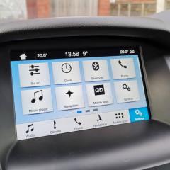
JPW Posted January 13, 2020 Author Share Posted January 13, 2020 Here is the pic of the LED switch I installed and wired up for the door lock function. Unlocked (off) and Locked (red) 2 Quote Link to comment Share on other sites More sharing options...
Monks600 Posted January 13, 2020 Share Posted January 13, 2020 Here is the pic of the LED switch I installed and wired up for the door lock function. Unlocked (off) and Locked (red)That looks really slick, good job! I really like it :)Sent from my iPhone using Tapatalk Pro Quote Link to comment Share on other sites More sharing options...
JPW Posted January 13, 2020 Author Share Posted January 13, 2020 Yep, really pleased with it. As I have enabled auto lock via Focccus, it lights up as soon as the car drives away and pressing it toggles the lock/unlock There is plenty of room under that little compartment for the switch and wiring. It's a 19mm version. I just spliced wires 2 and 6 from the FCIM and tapped in to the ground from the 12v socket next to it. https://www.amazon.co.uk/gp/aw/d/B07GLPBPPZ?psc=1&ref=ppx_pop_mob_b_asin_title Quote Link to comment Share on other sites More sharing options...
Monks600 Posted January 13, 2020 Share Posted January 13, 2020 Yep, really pleased with it. As I have enabled auto lock via Focccus, it lights up as soon as the car drives away and pressing it toggles the lock/unlock There is plenty of room under that little compartment for the switch and wiring. It's a 19mm version. I just spliced wires 2 and 6 from the FCIM and tapped in to the ground from the 12v socket next to it. https://www.amazon.co.uk/gp/aw/d/B07GLPBPPZ?psc=1&ref=ppx_pop_mob_b_asin_title Brilliant! I couldn’t get away with putting a button there, it’s my designated ecig holder lol! It literally fits perfectly and doesn’t rattle around! I’m going to keep my eyes out and do some searching for something that could go flush next to the traction control button as I have a blank space.Or, I may just convert the blank in to an actual button somehow :)Sent from my iPhone using Tapatalk Pro Quote Link to comment Share on other sites More sharing options...
Monks600 Posted January 14, 2020 Share Posted January 14, 2020 Not sure if I’m allowed to link to other forums but, this is a brilliant idea and this is exactly what I plan on doing.https://www.focusst.org/threads/how-to-make-a-blank-button-a-real-button-plenty-of-pics-and-a-video.46101/Sent from my iPhone using Tapatalk Pro 1 Quote Link to comment Share on other sites More sharing options...
Monks600 Posted January 15, 2020 Share Posted January 15, 2020 Not sure if I’m allowed to link to other forums but, this is a brilliant idea and this is exactly what I plan on doing.https://www.focusst.org/threads/how-to-make-a-blank-button-a-real-button-plenty-of-pics-and-a-video.46101/Sent from my iPhone using Tapatalk ProJust attempted the above and it worked flawlessly, I now have a factory/oem looking central locking button where the blank is next to ESC OFF. Absolutely made up! Sent from my iPhone using Tapatalk Pro 1 Quote Link to comment Share on other sites More sharing options...
JPW Posted January 15, 2020 Author Share Posted January 15, 2020 Nice. Any way to get the locking LED on it? Quote Link to comment Share on other sites More sharing options...
Monks600 Posted January 15, 2020 Share Posted January 15, 2020 Nice. Any way to get the locking LED on it?Yup, just an extra wire but didn’t have any more wire laying about. On the PCB behind the blank buttons there’s already led’s on there so I just need to sort a wire out to link between that and the front panel connector :) so surprised that it’s an actual button and simply filing a bit of plastic off gets it working! Sent from my iPhone using Tapatalk Pro Quote Link to comment Share on other sites More sharing options...
JPW Posted January 15, 2020 Author Share Posted January 15, 2020 So is it just filing the plastic to make it a button and then wire to the pins? Or do you need to mod the circuit board? Quote Link to comment Share on other sites More sharing options...
Monks600 Posted January 15, 2020 Share Posted January 15, 2020 So is it just filing the plastic to make it a button and then wire to the pins? Or do you need to mod the circuit board?Just file the plastic to remove the stoppers around the button and then this allows it to click in and out when pushed. I was missing the pin mentioned in that thread so I simply soldered a piece of wire directly to the PCB in place of the pin then routed it through the back of the plastic housing. Worked an absolute treat. If you want, you could solder a pin to the PCB which is really easy but i couldn’t find any laying about. Sent from my iPhone using Tapatalk Pro Quote Link to comment Share on other sites More sharing options...


Recommended Posts
Ford UK Shop
Sponsored Ad
Name: eBay
Ford Model: FordUK Shop
Ford Year: 2024
Latest Deals
Ford UK Shop for genuine Ford parts & accessoriesDisclaimer: As the club is an eBay Partner, The club may be compensated if you make a purchase via the club
Join the conversation
You can post now and register later. If you have an account, sign in now to post with your account.