Hamster Posted December 28, 2017 Share Posted December 28, 2017 Well, after many web orders and lots of returns I think I have found three satisfactory solutions for the appalling quality of front lighting on an LED‘less Edge. Easy one to start with, Front Fogs, carefully pull of the fog lamp cover towards the front of the vehicle, undo two small Torx screws and replace with LED H11 :-https://www.autobulbsdirect.co.uk/h11-twenty20-cree-led-12v-canbus-foglight-bulb.html The headlamps are a bit trickier. Whilst the back of the headlamp is accessible, there is not much finger room so I would advise taking out the whole headlamp and replacing the bulbs on a bench. There are two 10mm bolts to the top of the lamp assembly and a small plastic locating screw. Unclip the single wiring multi-plug. With these removed, gently tilt the headlamp up and back and pull it straight up. Be very careful of the painted bumper cover. The inner lights serve as Side lamps, DRL’s and Main beams. The bulbs are a bayonet fitting where the plug stays in place and are easily replaced with H15 :-https://www.ebay.co.uk/itm/H15-COB-LED-Headlight-Bulbs-Kit-20000-Lumens-Canbus-110W-DRL-Ford-Mercedes-BMW/282660230854?ssPageName=STRK%3AMEBIDX%3AIT&_trksid=p2060353.m2749.l2649 The outer lamps are the usual single use, double contact, H4 headlamp bulbs. These can be replaced as well with LED’s. The new LED's are held with the original springs but very tricky to get in so you have to unclip the spring completly from the top and wiggle it back in afterwards. https://www.ebay.co.uk/itm/H7-110W-LED-Headlight-Conversion-Kit-Car-Beam-Bulbs-Driving-Lamps-White-Bright/172764830065?ssPageName=STRK%3AMEBIDX%3AIT&_trksid=p2060353.m2749.l2649 I am very pleased with the result and this combination of bulbs give a good beam pattern and nice bright white light. If you do not feel confident in removing the lights a Dealer or friendly garage would help. H 1 Quote Link to comment Share on other sites More sharing options...
NeilRS Posted December 29, 2017 Share Posted December 29, 2017 Any pics of them with the lights on? 1 Quote Link to comment Share on other sites More sharing options...
Edge of Reason Posted December 29, 2017 Share Posted December 29, 2017 As per NeilRS above, before and after pics are a must, when trying to convince people to part with cash ! 😄 Quote Link to comment Share on other sites More sharing options...
Hamster Posted December 29, 2017 Author Share Posted December 29, 2017 You are not going to get before pics because its done now. You might get some after's though when it gets dark again. H Quote Link to comment Share on other sites More sharing options...
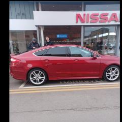
Hamster Posted December 29, 2017 Author Share Posted December 29, 2017 Ok, here is an 'after' pic. 1 1 Quote Link to comment Share on other sites More sharing options...
Jonro2009 Posted December 29, 2017 Share Posted December 29, 2017 I take it the H15 bulb is still a dual filament/chip set? Quote Link to comment Share on other sites More sharing options...
Hamster Posted December 29, 2017 Author Share Posted December 29, 2017 The H15 are LED's. They have three similar connectors to the OEM bulbs and have the three corresponding light levels. H 1 Quote Link to comment Share on other sites More sharing options...
NeilRS Posted December 29, 2017 Share Posted December 29, 2017 Thanks- they look great. Might give it a couple of weeks in case they melt your engine then I’ll order some! Quote Link to comment Share on other sites More sharing options...
Edge of Reason Posted December 30, 2017 Share Posted December 30, 2017 On 29/12/2017 at 1:48 PM, Hamster said: Ok, here is an 'after' pic. They certainly look much whiter and brighter than my yellowy candles. Has anyone flashed you due to being dazzled yet ? Quote Link to comment Share on other sites More sharing options...
Hamster Posted December 30, 2017 Author Share Posted December 30, 2017 Nope, not yet. Most of the time the vehicles that get flashed have incorrectly set up or adjusted headlamp aim. It really has to be done on an MOT ramp flat surface with a proper beam setter. Also, it's not just the height of the beam which is important also the horizontal aim. A lot of cars manufactured in Europe and further afield have the lamps set up as left hand drive which is wrong for the UK. It shouldn't matter how bright the lamps are, if the aim is good they won't dazzle. H Quote Link to comment Share on other sites More sharing options...
Jonro2009 Posted December 31, 2017 Share Posted December 31, 2017 Some of the aftermarket bulbs are rubbish even when correctly aligned and set up on an MOT standard rig. If the beam is scattered to begin with then you will never get it rightSent from my iPad using Tapatalk Quote Link to comment Share on other sites More sharing options...
Jonro2009 Posted December 31, 2017 Share Posted December 31, 2017 The H15 are LED's. They have three similar connectors to the OEM bulbs and have the three corresponding light levels. H 3 light levels? One pin will be an Earth and the others will be the positive feed. With the filament bulb there are two filaments, one for the DRL at 12w and the other is the high beam at 55w. What are the 3 light levels?Sent from my iPad using Tapatalk Quote Link to comment Share on other sites More sharing options...
Hamster Posted December 31, 2017 Author Share Posted December 31, 2017 I tested multiple bulbs, the rubbish ones with poor beam patterns went back. Yes, three light levels! The Edge has CAN-Bus wiring, which allows for (in a very simplified way) different voltages (possibly the same voltage, different power). Straight - standard voltages on vehicles is so yesterday. The three light levels are medium bright for the DRL's, these go a bit dimmer when the side lights are turned on and go a lot brighter when the main beam is on. H Quote Link to comment Share on other sites More sharing options...
Jim610 Posted December 31, 2017 Share Posted December 31, 2017 8 hours ago, Hamster said: I tested multiple bulbs, the rubbish ones with poor beam patterns went back. Yes, three light levels! The Edge has CAN-Bus wiring, which allows for (in a very simplified way) different voltages (possibly the same voltage, different power). Straight - standard voltages on vehicles is so yesterday. The three light levels are medium bright for the DRL's, these go a bit dimmer when the side lights are turned on and go a lot brighter when the main beam is on. H CAN-Bus does not mean variable voltage! Controller Area Network DataBus is a digital communications protocol used in vehicles. I'm fairly sure Edge Hallogen bulbs do NOT use CAN-Bus. Also, you can not vary the power without varying the current. That can only be done by varying either the Voltage or the load Resistance (Ohms Law). As I doubt they have found a way to vary the resistance of the bulbs at will then the only way to vary the power is the voltage. As it happens the 3 pins on the H15 are 1 x earth return and 2 x 12V supplies. One supplies the low power DRL element (Filament or LED) and the other supplies the higher powered Main Beam element therefore as the H15 is 2 bulbs in one the 3 light levels are Bright (Main beam), not so bright (DRL) and Off! I believe the LED lights fitted at build do use CAN-Bus. Have a happy new year. 1 Quote Link to comment Share on other sites More sharing options...
Hamster Posted December 31, 2017 Author Share Posted December 31, 2017 Well, whatever. Watt I do know is mine have three brightness's. There is only one 'ell in Halogen. I don't need to SHOUT the word 'not'. And, with regard to your last sentence, mine absolutely, definitely, without a shadow of a doubt, definitely, absolutely, have three brightness's :- DIM - Sidelights - no DRL MEDIUM - DRL BRIGHT - Main Beam Tomorrow, when it stops chucking it down, I'll post the lux levels of the three brightness's for you if you want. No need for an exclamation mark at the end! Nor did you have to capitalise off. Right now I'm off the find the wiring diagram to see if i can find a reference to CAN-Bus in the headlamp wiring. H Quote Link to comment Share on other sites More sharing options...
Hamster Posted December 31, 2017 Author Share Posted December 31, 2017 So, the headlamp wiring is connected to the BCM (Body Control Module)...................................................................... Even when they are Halogen and not OEM LED Adaptive Lamps. This is how CAN-Bus is explained. Overview Multiplexing is a method of sending 2 or more signals simultaneously over a single circuit. Multiplexing allows 2 or more electronic modules (nodes) to communicate over a twisted wire pair [data (+) and data (-)] network. The information or messages that can be communicated on these wires consists of commands, status or data. Multiplexing reduces the weight of the vehicle by reducing the number of redundant components and electrical wiring. The vehicle has 2 module communication networks connected to the DLC (data link connector), located under the instrument panel. The communication networks are: HS-CAN1 (high speed-controller area network 1) HS-CAN2 (high speed-controller area network 2) The vehicle has 2 module communication networks that communicate on the network, but do not communicate directly with the diagnostic scan tool. The GWM (gateway module A) translates the messages on these 2 networks, and transfers the signals to the HS-CAN2 to communicate with the diagnostic scan tool. The communication networks are: HS-CAN3 (high speed-controller area network 3) MS-CAN (medium speed-controller area network) This is how it works :- Network Termination The CAN (controller area network) uses network termination to improve communication reliability. Termination modules are located at both ends of the network. As network messages are broadcast in the form of voltage signals, the network voltage signals are stabilized by the termination resistors. Each termination module has an internal 120 ohm resistor that bridges across the positive and negative bus connection. With two 120 ohm resistors located in a parallel circuit configuration, the total network impedance, or total resistance, is 60 ohms. Network termination improves bus message reliability by stabilizing bus voltage and eliminating electrical interference. stabilizing bus voltage. eliminating electrical interference. The IPC, FCIM, PCM, SCCM and the GWM are termination modules, as shown in the system diagram. Gateway Module The GWM is mounted under the driver side instrument panel. The DLC is fitted to the GWM. The GWM acts as a central gateway to translate messages across all 4 vehicle controller area networks (CAN), and vice versa. The GWM is the only module on this vehicle with this ability. The 2 module communication networks connected directly to the DLC are HS-CAN1 and HS-CAN2. These 2 networks communicate directly with the diagnostic scan tool. The other 2 communication networks, HS-CAN3and MS-CAN, communicate on the network, but do not communicate directly with the diagnostic scan tool. The GWM translates the messages from these 2 networks to the HS-CAN2, which transfers the signals to the diagnostic scan tool. In total, 8 terminating resistors are installed. The two terminating resistors of the HS-CAN1 are incorporated in the PCM and in the GWM. The total resistance can be measured at the DLC between pins 6 and 14 and should be 60 ohms. The two terminating resistors of the HS-CAN2 are incorporated in the SCCM and the GWM. The total resistance can be measured at the DLC between pins 3 and 11 and should be 60 ohms The terminating resistors for the HS-CAN3 are located in the IPC and at the GWM. The total resistance should be 60 ohms. The MS-CAN terminating resistors are located in the FCIM and in the GWM. The total resistance should be 60 ohms. High Speed Controller Area Network 1 and 2 (HS-CAN1, HS-CAN2) TheHS-CAN1 and HS-CAN2 operate at a maximum data transfer speed of 500 Kbps and are designed for real time powertrain and driver feature information transfer and control. Modules on the HS-CAN1 and HS-CAN2 communicate using bussed messages. The HS-CAN uses an unshielded twisted pair cable, data bus (+) and data bus (-) circuits. In addition to scan tool communication, the HS-CAN allows sharing of information between all modules on each HS-CAN. With the addition of more modules, network traffic has increased. This has created the need for an additional HS-CAN to manage the increased bus data carried on each network. The GWM is used as a gateway for the messages to transfer between the scan tool and the modules on the HS-CAN1 and the modules on the HS-CAN2. The IDS (Integrated Diagnostic System) communicates with the vehicle communication networks directly through the HS-CAN1 and HS-CAN2. High Speed Controller Area Network 3 (HS-CAN3) The HS-CAN3 (HS-CAN Infotainment) operates at a maximum data transfer speed of 500 Kbps and is designed for real time audio, multimedia and driver information transfer and control. Modules on the HS-CAN3communicate using bussed messages. HS-CAN3 uses an unshielded twisted pair cable, data bus (+) and data bus (-) circuits, and allows sharing of information between all modules on the network. The GWM is used as a gateway for the messages to transfer between the IDS and the modules on the HS-CAN3. The GWM translates the diagnostic messages from the HS-CAN2 to the HS-CAN3 and vice versa, allowing communication beween the modules on the HS-CAN3 and the IDS. Medium Speed Controller Area Network (MS-CAN) The MS-CAN operates at a maximum data transfer speed of 125 Kbps and is designed for general information transfer. Modules on the MS-CAN communicate using bussed messages. The MS-CAN uses an unshielded twisted pair cable, data bus (+) and data bus (-) circuits. In addition to IDS communication, the MS-CAN allows sharing of information between all modules on the network. The GWM is used as a gateway for the messages to transfer between the IDS and the modules on the MS-CAN The GWM translates the diagnostic messages from the HS-CAN2 to the MS-CAN and vice versa, allowing communication between the modules on the MS-CAN and the IDS. LIN The transmission speed within the LIN databus system is 9.6 kBit/s. A LIN databus system consists of a LIN master and one or more LIN slaves. The LIN master knows the time sequence of all data which are to be transmitted. This data is transferred by the corresponding LIN slaves when they are prompted by the LIN master. The LIN data bus is a single conductor data bus system, i.e. the data is transmitted on one cable. No terminating resistors are used in the LIN network. So, CAN-Bus then. All this for three brightness's. You are correct with your three connectors, one could even be an earth, but undoubtedly three different light levels. Magic. H 1 Quote Link to comment Share on other sites More sharing options...
Jim610 Posted December 31, 2017 Share Posted December 31, 2017 Oh my! Sorry, didn’t mean to touch a sensitive spot. Thank you for your critique of my grammar, was never very talented in that area. I do however understand digital transmission techniques and data bus architectures, of which CANBus is but one of many. My main experience is in modern digitally controlled aeroplanes however, some of the smaller ones do use CANBus. I also know that a halogen bulb is a filament lamp using a tungsten wire in an Argon/Nitrogen gas mixture and that has no use of a digital message and purely needs a 12 volt DC power supply. You might be right about the 3 levels, I tend to be sat in the car when the lights are on and they do seem to have a mind of their own however the differences in brightness can only be a variation of Hi/Lo/Hi+Lo/off. See attached picture for H15 bulb pinout. No place for CANBus here just good old fashioned DC electrics. Quote Link to comment Share on other sites More sharing options...
Jonro2009 Posted January 1, 2018 Share Posted January 1, 2018 CAN-Bus does not mean variable voltage! Controller Area Network DataBus is a digital communications protocol used in vehicles. I'm fairly sure Edge Hallogen bulbs do NOT use CAN-Bus. Also, you can not vary the power without varying the current. That can only be done by varying either the Voltage or the load Resistance (Ohms Law). As I doubt they have found a way to vary the resistance of the bulbs at will then the only way to vary the power is the voltage. As it happens the 3 pins on the H15 are 1 x earth return and 2 x 12V supplies. One supplies the low power DRL element (Filament or LED) and the other supplies the higher powered Main Beam element therefore as the H15 is 2 bulbs in one the 3 light levels are Bright (Main beam), not so bright (DRL) and Off! I believe the LED lights fitted at build do use CAN-Bus. Have a happy new year. That’s what I was suggesting in my previous posts when I mentioned the pins, although I didn’t recognise OFF as one of the brightness levels. I believe that the H15 is monitored by the CANbus system as it will show as an error on the dash if one of those bulbs blows. I don’t believe that the aftermarket LED bulb should operate at 3 different levels as you say @Hamster I would not expect it to show a dim light when the sidelights are on, the car just isn’t programmed to work that way when it leaves the factory with Halogens. I wonder if the dim light is actually showing because there is still a small current running through the loom and it is enough to illuminate an LED but not enough for a Halogen bulb. It’s a common thing on interior aftermarket LEDs so I see no reason why it couldn’t happen elsewhere. Happy New Hear All [emoji313] Sent from my iPad using Tapatalk Quote Link to comment Share on other sites More sharing options...
Hamster Posted January 1, 2018 Author Share Posted January 1, 2018 By 'eck, you people don't half take some convincing. Whilst it's dark go out to your Edge (I know you have a Mondeo!) and take a willing volunteer with you. If you have auto lights turn them off. With the volunteer in the vehicle and you stood in front of the vehicle note the brightness of the two DRL, these are the ones towards the middle of the car. We can call this Middle Brightness number one. Get the volunteer to turn on the SIDELIGHTS and you WILL see the DRL go a bit dimmer. We can call this dim brightness number two. Now get the volunteer to turn on the headlamps, next notch round. You will see the outer lights come on, that's good. Now with the left hand stalk get the volunteer to flash (or push) the main beam on. You will see the DRL, centre, get brighter, brightness number three. Can then, the people with Edge's come on here and back me up? I can't believe you find it so hard. DRL brightness is the normal running state, put the sidelights on and this dims the DRL's a bit. Put the main beam on and this increases the DRL light levels a bit. It doesn't matter whether they are filament or LED the basic operation is exactly as it should be There is none of this residual current malarkey. It is as it should be. I do know, and have seen, this effect on inferior (not interior) LED replacements and it is not this. Quite honestly, with my Ford experience, I am usually the one answering the questions and not defending my position. I'm new to this particular forum as I've just bought an Edge and I know I have a particular style of posting but as you will soon hopefully agree I do know my stuff when it comes to Ford and their vehicles. Whether or not you choose to 'believe' me is your choice but I know absolutely, that I am right. H Quote Link to comment Share on other sites More sharing options...
Wizzo Posted January 1, 2018 Share Posted January 1, 2018 Thanks for all your info on the LED's Hamster. I will be looking into these myself 👍 1 Quote Link to comment Share on other sites More sharing options...
xn85 Posted January 1, 2018 Share Posted January 1, 2018 I might be completely misreading this thread, but think there might be two conversations going on... One seems to be saying that the DRL / Main beam bulb also functions as a parking light. This latter function is traditionally served by a 5w bulb and is too pathetic to be used as anything other than a ‘marker lamp’ to (hopefully) prevent someone running into you whilst parked. People who insist in driving using only their parking lights are a real hate of mine, so my apologies. I digress... The multi functions are all served by the same, twin filament (15/55w) H15 bulb... On my car, I can confirm that the lamp alongside the dipped beam does vary in brightness between parking light, dimly lit (DRL) and slightly brighter (main beam). The second conversation appears to me to be HOW the bulb manages to achieve all these settings. I’m not technical and do find it confusing how you can get three light settings out of one bulb, with two filaments. The answers to this i’m finding quite interesting and can almost understand them! Thanks guys! My own theory relating to the headlights on the Edge involves pixies and candles, but this might be a result of my bitterness at not getting a car with the factory fit LEDs... Please correct me if I’m wrong, but if not, then you are all correct! Quote Link to comment Share on other sites More sharing options...
JW1982 Posted January 1, 2018 Share Posted January 1, 2018 The standard halogen headlights of most Ford models are controlled by using a PWM (Pulse Widt Modulation) signal. The PWM signal basically switches the lights on and off continuously at a very high frequency (which is not visible for the human eye). By adjusting the width of the pulses the light output of the lights can have different intensities. PWM is used on modern Ford models to improve the life expectancy of the halogen light bulbs and to use the same light bulb for 2 (or more) different functions. Unfortunately the PWM signal can seriously affect the life expectancy of HID bulbs and LED Bulbs with integrated voltage regulators.. 1 Quote Link to comment Share on other sites More sharing options...
Hamster Posted January 1, 2018 Author Share Posted January 1, 2018 Well, we are getting there. My generation (old but not retired yet) remember parking lights as one set of one side, front and back lights used when parking. Not common and rarely used. Sidelights, however are the bread and butter of lights. Most vehicle headlamps have three positions/phases/switches, whatever. When you are driving along and it starts to get dark you put on your sidelights, you could call them dim. When it gets a bit darker you put on your headlamps and pootle along with them dipped around town etc. On the open road you can use the third phase, or main/high beam. Unless it's a Corsa and then the only one is high beam and the requirement is to wear a cap backwards. C'mon folks if you've passed your driving test in the last 50 years, surely I don't have to describe this!! H 1 Quote Link to comment Share on other sites More sharing options...
Jim610 Posted January 1, 2018 Share Posted January 1, 2018 2 hours ago, Hamster said: By 'eck, you people don't half take some convincing. Whilst it's dark go out to your Edge (I know you have a Mondeo!) and take a willing volunteer with you. If you have auto lights turn them off. With the volunteer in the vehicle and you stood in front of the vehicle note the brightness of the two DRL, these are the ones towards the middle of the car. We can call this Middle Brightness number one. Get the volunteer to turn on the SIDELIGHTS and you WILL see the DRL go a bit dimmer. We can call this dim brightness number two. Now get the volunteer to turn on the headlamps, next notch round. You will see the outer lights come on, that's good. Now with the left hand stalk get the volunteer to flash (or push) the main beam on. You will see the DRL, centre, get brighter, brightness number three. Can then, the people with Edge's come on here and back me up? I can't believe you find it so hard. DRL brightness is the normal running state, put the sidelights on and this dims the DRL's a bit. Put the main beam on and this increases the DRL light levels a bit. It doesn't matter whether they are filament or LED the basic operation is exactly as it should be There is none of this residual current malarkey. It is as it should be. I do know, and have seen, this effect on inferior (not interior) LED replacements and it is not this. Quite honestly, with my Ford experience, I am usually the one answering the questions and not defending my position. I'm new to this particular forum as I've just bought an Edge and I know I have a particular style of posting but as you will soon hopefully agree I do know my stuff when it comes to Ford and their vehicles. Whether or not you choose to 'believe' me is your choice but I know absolutely, that I am right. H Hamster I've just done as you suggested and you are correct there are 3 light levels. Referring to the diagram below (you know I love diagrams); with the light switch off Filament 1 is at full brightness (well, as bright as it can be), with the light switch at Side lights Filament 1 is at what appears to be half brightness, with the light switch at head lights (dipped), Filament 1 is as above and the other bulb comes on, with the head lights selected to Main beam Filament 2 lights up as its full intensity. So, Filament 1 has two distinct levels. They may be controlled by PWM, as stated above, or simply by supplying them with a reduced voltage, via a resistor in series perhaps. Either way it has nothing to do with CANBus, which is where this conversation seemed to lose track. A H15 bulb has no CANBus Nod circuitry inside to communicate with the CANBus. Also, have you noticed if you indicate the DRL/Sidelight on that side extinguishes when the indicator is flashing? Quote Link to comment Share on other sites More sharing options...
simonb65 Posted January 1, 2018 Share Posted January 1, 2018 1 hour ago, Jim610 said: A H15 bulb has no CANBus Nod circuitry inside to communicate with the CANBus. Just to clarify to those that think 'CANbus' lamps are technologically advanced ... they are not! To explain what this mis-used terminology actually means is that LED lamps naturally draw much less current than a standard filament lamp. Thus the ECU that drives the lamp sees a standard LED as a low current draw and thinks its a filament lamp that has blown. To stop the ECU seeing a smaller current draw, a resistor is placed in parallel with the LED to bring the current draw back above the error detection theshold. the CAN network only gets to know about the bulb state when the ECU transmits its state onto the CANbus. THERE IS NO DIRECT LINK BETWEEN AN LED AND CANBUS. THEY ARE NOT 'SMARTER' LAMPS. Sorry, just had to clarify. I've been in the automotive electronics and networks business for 20 years now and the term CANbus in relation to a lamps spec just drives me mental! </minor rant over> 1 Quote Link to comment Share on other sites More sharing options...


Recommended Posts
Ford UK Shop
Sponsored Ad
Name: eBay
Ford Model: FordUK Shop
Ford Year: 2024
Latest Deals
Ford UK Shop for genuine Ford parts & accessoriesDisclaimer: As the club is an eBay Partner, The club may be compensated if you make a purchase via the club
Join the conversation
You can post now and register later. If you have an account, sign in now to post with your account.